Introduction
Before you dive into Revit, you need to speak the language of architectural drawings. Every drawing communicates through a shared visual vocabulary - symbols, notations, view types, and conventions that architects, engineers, and contractors have used for decades. This guide decodes that vocabulary.
1. View Types: Plan, Section, and Elevation
Understanding the three fundamental view types is the foundation of reading any set of construction documents.
Floor Plan
A floor plan is a horizontal cut through the building, typically at 1.2 m (4 ft) above the floor. Everything below the cut is shown; walls that are cut through appear as thick solid lines (or with hatch fill); elements above the cut - high windows, overhead features - appear as dashed lines.

Section (חתך)
A section is a vertical cut through the building. It reveals interior heights, floor-to-floor dimensions, staircase relationships, and structural elements. The cut line is shown on the floor plan with a section marker - two arrows pointing in the direction you are looking.
Key rule: What is cut shows as solid/filled; what is visible behind the cut shows as lighter lines.
Elevation (חזית)
An elevation is an orthographic (flat, no perspective) view of a facade or interior wall, viewed straight on. No cuts are made - you see the face of the wall, door and window heights, material finishes, and vertical dimensions.
| View Type | What is cut | What you see | Typical use |
|---|---|---|---|
| Floor Plan | Horizontal cut at ~1.2 m | Layout, room sizes, wall thickness | Every sheet set |
| Section | Vertical cut through building | Heights, structure, floor builds | Structural & detail sheets |
| Elevation | No cut - looking at a face | Facade finishes, openings, heights | Exterior/interior design |
2. Wall Markings and Notations
Walls in architectural drawings carry a lot of information through their symbols.
Wall Types by Hatch Pattern
Different hatch patterns inside a wall section indicate the construction material:
| Hatch Pattern | Material |
|---|---|
| Solid black fill | Concrete or masonry (in section) |
| Diagonal lines (45°) | Brick / block |
| Parallel horizontal lines | Insulation / lightweight partition |
| No fill, just outline | Stud / gypsum partition wall |
| Cross-hatch | Earth / backfill |
Wall Tags and Type Marks
In Revit, every wall type carries a Type Mark (e.g., W1, W2, EW-200) that links to a wall schedule. You'll see these tags floating beside the wall in plan - click them and a schedule shows thickness, layers, and fire rating.
Interior vs. Exterior Walls
- Exterior walls are thicker and often carry more complex hatch patterns with insulation and cladding layers
- Interior partition walls are thinner (often 100–150 mm) and shown with simpler outlines
3. Common Architectural Symbols
North Arrow
Every floor plan must include a north arrow. In Revit it's placed on the sheet, not in the model - so it rotates when you rotate the view crop.
Grid Lines
Structural grid lines are numbered (1, 2, 3…) in one direction and lettered (A, B, C…) in the other. Columns, beams, and walls are located relative to grid intersections. Grids appear as long dashed lines with circle "bubbles" at each end showing the grid label.
Section Marker
A section marker on a floor plan shows where a section cut is taken. It consists of:
- A dashed line showing the cut plane
- Two filled arrowheads pointing in the viewing direction
- A reference number (sheet number / detail number) in the circle
Elevation Marker
An elevation marker is usually a diamond or circle on the floor plan with arrows pointing toward each wall being shown. The label references the sheet and view number where that elevation appears.
Door Symbol
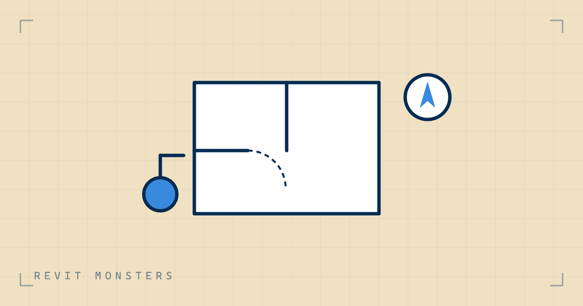
In plan, a door is shown as a thin line (the door leaf) with a quarter-circle arc showing the swing direction. Pocket doors and sliding doors use different conventions (parallel dashed lines).
Window Symbol
In plan, a window is shown as three thin parallel lines within the wall thickness - representing the two panes and the frame.
4. Dimensions and Tags
Dimension Strings
Dimensions in architectural drawings come in chains:
- Overall dimension - total length of a wall or building face (outermost string)
- Intermediate dimensions - distances to openings, offsets, partitions (inner strings)
- Small dimensions - opening widths, exact setbacks (innermost string)
Dimension lines end in either tick marks or arrowheads depending on office standard. The number sits above the line (ISO/European convention) or inside a break in the line (US convention).
Room Tags
Each room in a Revit floor plan carries a room tag showing:
- Room name (e.g., "Living Room")
- Room number (e.g., "101")
- Area (optional, e.g., "22.5 m²")
Room tags are linked to the Room object - change the name in the tag and it updates in schedules automatically.
Door and Window Tags
Every door and window carries a tag that references its mark (D1, W3, etc.). These marks link to door and window schedules that list dimensions, frame material, glazing type, and hardware.
Spot Elevations
Spot elevations are small triangular symbols that annotate a height value at a specific point - floor level, slab soffit, top of wall, etc. In Revit, these update automatically when the model changes.
5. MEP Discipline Symbols
MEP stands for Mechanical, Electrical, and Plumbing - the building services that make a structure livable. Each discipline has its own layer and its own symbol vocabulary.

Plumbing (אינסטלציה)
Plumbing drawings show supply lines, drain lines, and fixture locations.
| Symbol | Meaning |
|---|---|
| Solid blue line | Cold water supply |
| Solid red line | Hot water supply |
| Dashed green line | Drain / waste line |
| Circle with cross | Floor drain |
| Rectangle (plan) | Toilet / WC |
| Oval (plan) | Sink / basin |
| Rectangle + lines | Shower tray |
| Triangle | Cleanout access point |
Pipe diameters are annotated alongside the line (e.g., "Ø50 PVC" or "DN25 copper"). Slopes on drain lines are noted as a ratio (e.g., 1:50 = 2% grade).
HVAC / Air Conditioning (מיזוג אוויר)
HVAC drawings cover heating, ventilation, and air conditioning - ducts, diffusers, fan coil units, and ductwork routing.
| Symbol | Meaning |
|---|---|
| Rectangle with X | Ceiling supply diffuser |
| Rectangle with lines | Linear slot diffuser |
| Circle with crosshairs | Circular diffuser |
| Dashed rectangle | Return air grille |
| FCU label | Fan Coil Unit |
| Wide duct line | Main supply duct |
| Narrower duct line | Branch duct |
| Triangle in duct | Direction of airflow |
Duct sizes are noted as width × height (e.g., "400×200") or as a diameter for round ducts ("Ø315").
Electrical (חשמל)
Electrical drawings show power circuits, lighting circuits, switch layouts, and panel locations.
| Symbol | Meaning |
|---|---|
| Circle with lines | Ceiling light fixture |
| Solid circle | Recessed downlight |
| S (on wall) | Single switch |
| S₂ | Two-way switch |
| Rectangle (on wall) | Electrical outlet / socket |
| ⊕ | Earth / ground point |
| Panel rectangle | Distribution panel |
| Dashed arc | Conduit / cable run (hidden) |
Circuit numbers (e.g., C1, L3) are noted next to each fixture or outlet. Panel schedules list every circuit: breaker size, load, and what it serves.
Structural (קונסטרוקציה)
Structural drawings show columns, beams, slabs, foundations, and reinforcement.
| Symbol | Meaning |
|---|---|
| Solid square / rectangle | Concrete column |
| X in square | Steel column |
| Heavy dashed line | Concrete beam below slab |
| Diagonal lines on slab | Span direction indicator |
| Ø or # | Rebar diameter (e.g., Ø16, #5) |
| @ | Spacing (e.g., Ø12@200 = 12 mm bars at 200 mm centers) |
| T | Top reinforcement layer |
| B | Bottom reinforcement layer |
Structural drawings also include section details showing rebar placement, cover dimensions, and lap lengths.
6. Drawing Sheets and Title Blocks
Every professional drawing sheet includes a title block with:
| Field | Purpose |
|---|---|
| Project name | Identifies the building |
| Drawing title | What this sheet shows |
| Sheet number | e.g., A-101, S-201, M-301 (A=Architectural, S=Structural, M=Mechanical) |
| Revision cloud | Area of changes, with revision letter/date |
| Scale | e.g., 1:100, 1:50 |
| North arrow | Orientation reference |
| Drawn by / Checked by | Responsibility tracking |
| Issue date / Revision dates | Document control |
Revit's sheet system manages title blocks automatically - fill in the project info once and every sheet updates.
Summary
Mastering architectural drawing conventions transforms how you use Revit. You're not just placing walls and doors - you're communicating with a team across disciplines. Every hatch, every tag, every symbol is a word in a shared professional language. The next step: open a real set of construction documents and identify each element you've learned here. Practice reading before you start drawing.
Want to produce these drawings yourself, not just read them? That is exactly what our Revit courses teach, step by step.